Overview
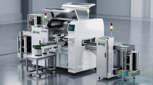
An odd-form insertion machine is used to automate selected through-hole component handling and insertion tasks that are difficult to standardize with one feeding and tooling arrangement. The project category is odd-form insertion automation. The final machine configuration is defined only after reviewing the component, incoming packaging, PCB, current process, target capacity and available samples.
Suitable component families
Potential component families include:
- connectors and terminals;
- relays and switches;
- power components such as selected capacitors, inductors and fuse holders; and
- other large or non-standard through-hole components.
These families are starting points for evaluation. Component geometry, lead condition, orientation, packaging and insertion requirements determine whether a specific part is suitable.
Line workflow
A project review normally maps the required workflow from incoming material to an agreed insertion result:
- Confirm the incoming component and its packaging condition.
- Evaluate singulation, orientation and presentation at the pickup point.
- Define the feeder interface, end tool and component handling sequence.
- Review PCB positioning, hole data, underside clearance and board support.
- Define insertion, presence or process checks that are appropriate to the approved configuration.
- Plan changeover, operator tasks and acceptance evidence for the intended production mix.
Each stage depends on engineering evaluation. This workflow does not confirm a standard machine capability for an unreviewed component.
Feeder and end-tool relationship
The feeder, presentation point and end tool must be considered as one handling chain. A feeder must present the component in a controlled orientation, while the end tool must pick or hold it without creating unacceptable contact, deformation or loss of orientation. The interface also has to match the component’s insertion direction and PCB access conditions.
Standard feeding, bowl or flexible feeding, and customized feeding are possible evaluation routes. The route is not confirmed until the actual component and packaging have been reviewed. See Feeder Solutions for the engineering boundaries of each category.
PCB support and insertion conditions
PCB support is evaluated around the component footprint and insertion area. The review considers board size and thickness, nearby components, underside clearance, fixture access, board flex risk, hole position and the component’s lead geometry. Support and locating details are therefore project-specific.
Changeover planning
Changeover planning starts with the customer’s product mix. Engineering needs to compare the components, feeders, end tools, PCB supports, programs and verification steps that may change between products. The resulting changeover method and scope must be agreed during project evaluation; no changeover time is claimed without a named, approved configuration source.
Sample validation and FAT path
The normal validation path is:
- Document review: confirm component, packaging, PCB and process information.
- Sample review: inspect representative components and boards for handling and insertion risks.
- Engineering proposal: define the proposed feeding, tooling, PCB support and evaluation boundaries.
- Trial and acceptance planning: agree which samples, operating conditions and evidence will be used.
- FAT preparation: confirm the approved scope, sample quantity, test method and acceptance criteria before factory acceptance testing.
Feasibility, final configuration and FAT results remain subject to the reviewed samples and agreed acceptance criteria.
Information required for evaluation
Please provide:
- PCB photo;
- component photo;
- part number or list;
- packaging details;
- current process;
- target capacity;
- pain point;
- sample availability; and
- timeline.
This information allows the engineering team to identify open questions and propose the next evaluation step without making an early capability promise.